Assembly, inspection, electrical verification, initial power-up, and field testing of a compact QRP transceiver.
Project Overview
This project documents the assembly and initial testing of a QMX low-power HF transceiver. It provided hands-on experience with component handling, precision soldering, PCB inspection, electrical verification, and methodical power-up procedures.
Hardware and Tools
QMX HF transceiver kit
Soldering station
Digital multimeter
USB microscope
Programmable DC power supply
Computer for configuration and testing
Skills Developed
Component identification
Precision soldering
Microscope-assisted inspection
Electrical testing and safe power-up
Troubleshooting and documentation
Build Process
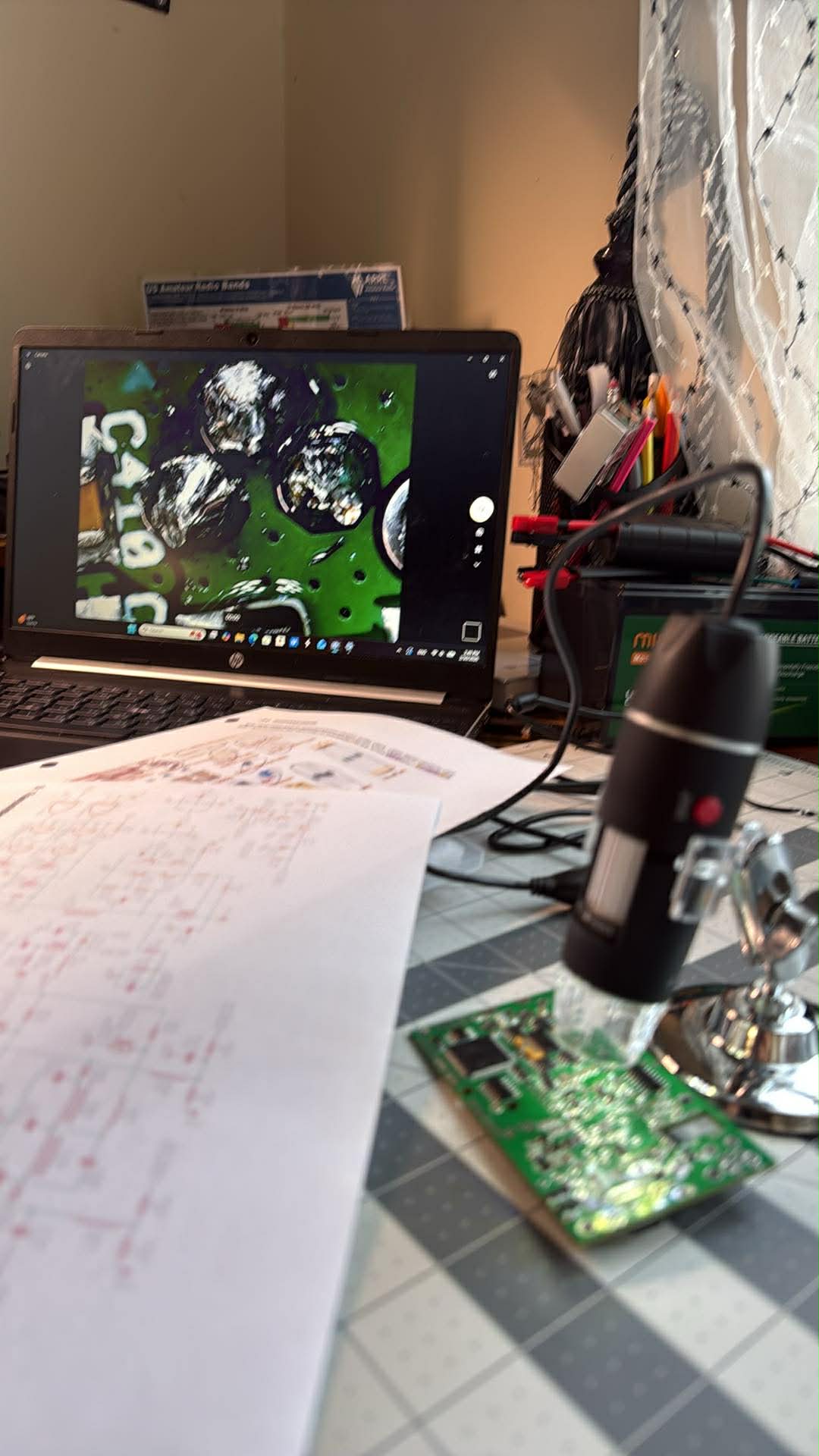
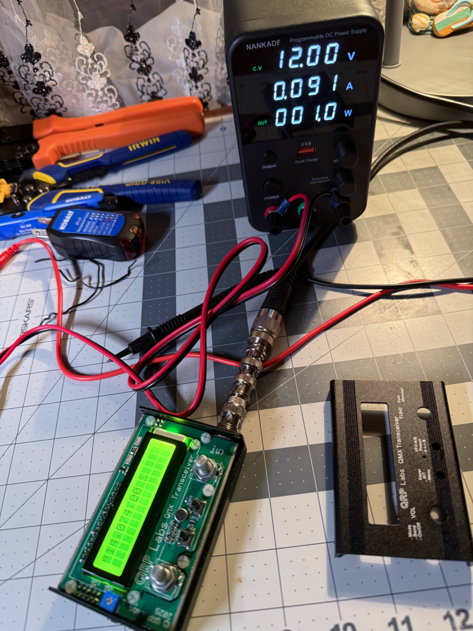
The kit was assembled by carefully installing and soldering the required components. After assembly, the PCB was inspected under magnification to check solder joints, alignment, and possible bridging. Electrical checks were completed before applying power, followed by controlled initial power-up and functional verification.
QMX Field Testing
Lessons Learned
The project improved my understanding of transceiver construction, component functions, inspection standards, and the importance of controlled testing. Patience, precision, and a step-by-step troubleshooting method were essential. The project focused on assembly, electronics, configuration, and functional verification; antenna design was outside its scope.